


Introduction
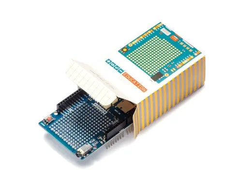
The Education Shield is a custom-made shield designed by Arduino Education, specially tailored for educational purposes to enable quick and easy learning while building projects. The shield is meant to be used in conjuction with . It connects to an Arduino 101 or UNO and extend their capabilities. The shield has a collection of features that make building small projects in or outside of the classroom easy:
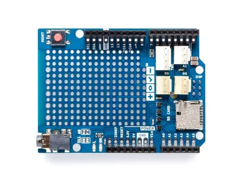
- Reset button. When this is pressed the program uploaded to the control board is restarted.
- Built in protoshield or used as a placement of breadboard.
- Digital input and output pins. Directly connected to the digital pins on the board.
- I2C connector.
- A1 3-pin header port: Analog out/in. This can also be .
- D6 and D9: digital 3-pin header ports connected to digital pin 6 and 9.
- Speaker plug:This is connected to digital pin 11.
- Ground and power pins. The voltage supply pin used in CTC is the IOREF pin. This pin outputs different voltages depending on the board (101 board: 3.3V, UNO board: 5V).
- Analog input/output pins.
- SD card reader/writer connected to digital pins 10 to 13.
Note:
- Avoid using analog A4 and A5. These have pull-up resistors connected to them and you should avoid using unless you know what you are doing.
- Do not use digital pins 4, 10, 11, 12 and 13 when using the micro SD card reader.
- Digital pins 9 to 13 cannot be used for capacitive sensors, these are connected to the SD card reader which has resistors and might therefore provide false readings.
- Digital pin 6, 9 and analog pin A1 are connected to component module ports. If the ports are used don’t use the corresponding pins.
- Digital pin 11 is connected to the audio socket. If the socket is in use don't use the pin.
Use Modules with simple connectors
A simple 3 pin connector, that snaps in place, is used for all 3-pin modules. Here are some examples of components All these make connecting and prototyping easier through their simplified design: Push button modules, light sensor modules, and power LED modules.
If you’re trying to connect servos or other 3-pin modules, be sure about the direction of the connector so that GND is connected to GND, power to power and signal to signal. The color of a simple connector wire helps you remember it: red means power, orange or white means signal, and black means GND. Technically you can connect modules with simple connectors without 3-pin ports, as long as you plug the wires to the right pins.
OSH: Schematics
The Arduino Education Shield is open-source hardware! You can build your own board using the following files:


![Furuno DRS25AX 25kW UHD Digital Radar w/Pedestal, 15M Cable 4 Open Array [DRS25AX/4]](https://www.advancetedsecu.shop/image/furuno-drs25ax-25kw-uhd-digital-radar-wpedestal-15m-cable-4-open-array-drs25ax4_8hPmhz_285x.webp "Furuno DRS25AX 25kW UHD Digital Radar w/Pedestal, 15M Cable 4 Open Array [DRS25AX/4]")
")
 7SF-000-AO")


